In engineering, materials can be categorised according to their microscopic structure: : 15–17 The structure and composition of a material can be determined by microscopy or spectroscopy. The relevant structure of materials has a different length scale depending on the material. Material selection is a process to determine which material should be used for a given application. Biomaterials are used for applications interacting with living systems.Aerospace materials are used in aircraft and other aerospace applications.Nuclear materials are used for nuclear power and weapons.Refractory materials are used for high-temperature applications.Building insulation materials are used to retain heat within buildings.

Building materials are used for construction.JavaScript - index.html var material = new THREE.Materials can be broadly categorized in terms of their use, for example: If you're targeting a different shading language and don't have the reflect() function, you can replace it with the equivalent expression r = e - 2.
#MATCAP DOWNLOAD CODE#
This tutorial is based on the GLSL language to code the shader.

Once we have both vectors, we calculate the reflected vector.

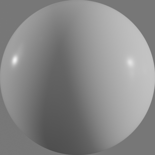
We need to convert the 3-dimensional position into a 4-dimensional vector to be able to multiply it by the matrices. Eye is the vector that goes from the camera (a point in space at the origin) to the fragment position. So first we need to set up two vectors, e (Eye) and n (Normal). Normals looking upwards (we're talking screen space so "up" is towards the physical top of the screen) are mapped to the top of the matCap texture normals looking downwards, to the bottom. In order to understand SEM spatially, assume that surfaces looking straight into the camera (the normal vector is parallel to the camera vector) is mapped to the texel right in the middle of the matCap texture and as the normal vector diverges from the camera vector (the angle between both vectors tends to 90º) the texel is looked up more towards the borders. That can be done in the vertex shader -and let the GPU take care of the interpolation- or in the fragment shader. The main idea of SEM is to get the UV coordinates (which are used to lookup the matCap texture) from the normal vector on the fragment instead of the original texture coordinates from the object. All we can emulate is an object rotating by itself in a still light and camera setup. That’s why it doesn’t work as a perfect environment map: it doesn’t rotate with the view because it’s missing part of the information.

The sphere map contains everything that is in front of the camera, which means that the texture contains the incoming light inciding in the surface facing the camera. These are essentially spherical reflection maps, but with a more diffuse colour instead of a sharp image. SEM uses special texture maps called “lit spheres” or “matcaps”.
#MATCAP DOWNLOAD SOFTWARE#
This technique has been popularised by software like Pixologic ZBrush or Luxology Modo. Spherical reflection (or environment) mapping (SEM) is a fast way to fake the specular term of the lighting equation, and for specific cases, to fake lighting altogether. It takes a lot of calculations, setup and tweaking to get surfaces to look realistic and convincing. One of the most important aspects of computer-generated images is lighting. Low quality, code might be outdated, and some links might not work. This is a legacy post, ported from the old system: Article | Posted on September 2013 Creating a Spherical Environment Mapping shader


 0 kommentar(er)
